In this post
Light waves are examples of transverse waves. They always travel in straight lines and, like all waves, can be reflected or refracted.
Reflection
If light waves strike a surface they will be reflected. This allows us to see objects using our eyes. Reflection of the light waves causes them to bounce off from the surface and change direction. The angle at which the waves bounce off, and direction in which they move, depends upon the surface of the material and the angle at which they were first sent towards the surface.
There are two types of reflection to be aware of. The first of these is diffuse reflection which occurs when light waves are reflected off a rough surface. In diffuse reflection, the light waves are reflected off the surface in lots of different directions. The reflections seen will be very fuzzy and difficult to make out.
The second type is specular reflection which occurs when light hits a shiny and flat plane surface, such as a mirror. The light that is reflection all travels in a single direction so the image produced is sharp and focused. The reflected images formed in a mirrored surface have the following properties:
- The image is as far behind the mirror as the object is in front of it
- The image is always the same size as the object
- The image cannot be produced on a screen and is virtual
- The image is inverted laterally and this means that the left and right side of the image are interchanged
- The image is always the correct way up
In specular reflection the angle at which the light wave is reflected should be equal to the angle at which the light waves initially hit the surface. This relationship can be tested and investigated using a light box, mirror, plain paper and a protractor.
The paper is placed flat on the surface of the desk and the mirror is placed at the edge of the paper furthest away. The light box is used to direct a beam of light towards the mirror. This ray of light moving towards the mirror is known as the incident ray.
The light is then bounced off from the surface of the mirror. This is known as the reflected ray. We then draw a horizontal line onto the plain paper. This line must be drawn perpendicular to the mirror’s surface and start at the point where the incident ray hits the surface. This line is known as the normal. The angle between the incident ray and the normal can then be measured using the protractor. This angle is known as the angle of incidence. The angle between the reflected ray and the normal can also be measured using the same protractor. This angle is known as the angle of reflection. The angles of incidence and reflection are measured using a protractor and quoted using the unit degrees (o). When light is reflected from a flat, shiny surface, the angle of incidence should always be equal to the angle of reflection. This rule is known as the law of reflection.
For example, if the incident ray hits the mirror at an angle of 40o, the reflected ray should also be reflected from the mirror at an angle of 40o. We represent the effects of reflection using a ray diagram where the light waves are represented using a ray drawn as a single line. The incident ray is drawn with an arrowhead somewhere along the line to indicate that the light is moving towards the mirror. The mirror is drawn as a straight line and the normal is represented using a dashed line. The reflected ray is also drawn as a straight line with an arrowhead positioned away from the mirror to show the ray being reflected away from the surface
The angles of incidence and reflection must look equal on the drawing to illustrate the effects of the law of reflection.
A typical ray diagram used to illustrate reflection is shown below.
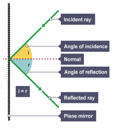
The angle of incidence is always equal to the angle of reflection when a plane mirrored surface is used. This law of reflection allows us to use equipment such as periscopes to view places which we may not be able to see just by using our own eyes.
Light travels in straight lines only so we are only able to see someone with our naked eye if the object is directly in our line of sight. For example, we cannot see an object around a corner or on a surface above our head.
Periscopes are often used in submarines. As the submarine is below the surface of the sea, the crew are unable to look out of the windows to see if there are any other boats above them. The crew from the submarine sends the periscope up through the water so that they can see what is out on the surface of the sea. The light waves reflected off boats or other objects strike a mirrored surface inside the periscope. This surface is placed at a slight angle so that the reflected rays can be sent down the tube of the periscope. The light ray enters at an angle of 45o to the normal and will therefore be reflected off at an equal angle of 45o. As the mirror is already angled, the light is reflected down the periscope. The ray then hits a second mirror placed at the bottom of the periscope at an angle of 90o. The light is reflected off this mirror at an equal angle of 90o and into the crew member’s eyes, as shown in the diagram below:
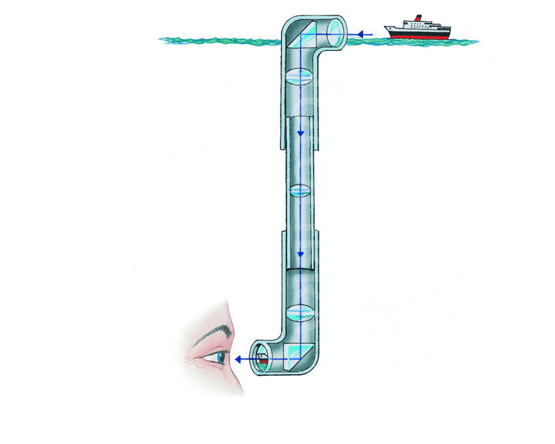
Periscopes could also be used to see objects that are around the corner of a building.
Refraction
The speed of light through a vacuum is 3 x 10⁸ m/s. However, light travels much more slowly through water with a speed of 2.25 x 10⁸ m/s.
When light travels through the air and into water, there is a change of speed as the light waves cross the boundary between the two different mediums. A medium is a material such as glass or water. The slowing down of the light causes it to change direction or ‘bend’. Light rays bend and change direction as they travel between different mediums.
This changing of direction is known as refraction. As a ray of light enters a medium, it will slow down and will be refracted towards the normal. As the ray leaves the medium, it will speed up and refract away from the normal.
Dispersion
You can investigate the refraction of light using a variety of different glass blocks such as rectangles, semi-circular blocks and triangular prisms. If white light is directed into a triangular prism, a special type of refraction occurs where the white light is split into the seven colours of the spectrum of white visible light, as shown in the diagram below:
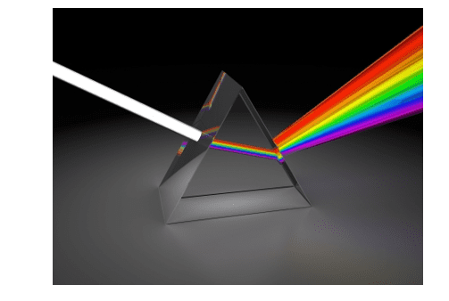
This splitting of the visible light is known as dispersion. The spectrum produced is made up of the following colours:
- Red
- Orange
- Yellow
- Green
- Blue
- Indigo
- Violet
The spectrum is produced because of the different speeds that light travels at. Each colour has a slightly different wavelength and frequency and therefore travels at a slightly different speed. This results in each colour refracted at a different angle, resulting in the slight deviation in the direction in which each colour travels and allowing the colours to spread out to produce the spectrum.
Refraction can be investigated using a light box, rectangular glass (or Perspex) block, plain paper and a protractor. The rectangular glass block allows us to see the light ray pass through its boundaries. We can therefore trace the path taken by the ray of light and, using the normal and a protractor, we can measure the angle of incidence (i) and angle of refraction (r).
The Perspex block is placed in the middle of the plain paper and the light box is used to direct the incident ray into the block. As the incident ray enters the Perspex block, it slows down and is refracted towards the normal to produce a refracted ray inside the Perspex. This refracted ray moves through the Perspex and comes out of the other side as an emergent ray. As the emergent ray leaves the medium, it speeds up and refracts away from the normal, as shown in the diagram below.
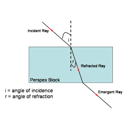
For refraction the angle of incidence is never equal to the angle of refraction. We can investigate how the angles of incidence and refraction are related by repeating the measurements using a wide range of angles of incidence.
From the results of such experiments we know that the amount of refraction which occurs is dependent upon the angle of incidence and the difference in the densities of the different types of medium.
The refractive index of a medium gives us a measure of the degree to which it is able to slow down the speed of light travelling through it.
We can calculate the refractive index of any material providing that the angles of incidence and refraction have been measured. The equation used to show the relationship between refractive index, angle of incidence and angle of refraction is:
![Rendered by QuickLaTeX.com \[ \text{n} = \frac{sin i}{sin r} \]](https://b3801007.smushcdn.com/3801007/wp-content/ql-cache/quicklatex.com-7c5b48d8713276d75ec808035b262576_l3.png?lossy=2&strip=1&webp=1)
where n is refractive index,
sin i is the sin of the angle of incidence
and
sin r is the sin of the angle of refraction.
You must know and be able to use this equation as it will not be provided in the exam.
Example
In an experiment the angle of incidence is measured as 70o and the angle of refraction measured as 48o. Calculate the refractive index of the Perspex block.
Firstly, we write down the equation needed:
![Rendered by QuickLaTeX.com \[ \text{n} = \frac{sin i}{sin r} \]](https://b3801007.smushcdn.com/3801007/wp-content/ql-cache/quicklatex.com-7c5b48d8713276d75ec808035b262576_l3.png?lossy=2&strip=1&webp=1)
Then we substitute in the values from the question:
![Rendered by QuickLaTeX.com \[ \text{n} = \frac{sin 70}{sin 48} \]](https://b3801007.smushcdn.com/3801007/wp-content/ql-cache/quicklatex.com-ce291ae1351a88e6c753c903ffc1f9ba_l3.png?lossy=2&strip=1&webp=1)
Use the sin button on your calculator when typing in the equation
![Rendered by QuickLaTeX.com \[ \text{n} = \frac{0.940}{0.743} \]](https://b3801007.smushcdn.com/3801007/wp-content/ql-cache/quicklatex.com-9d0b118c7b5d829834ce706f17fe2584_l3.png?lossy=2&strip=1&webp=1)

